Council on Energy, Environment and Water Integrated | International | Independent
Suggested Citation: Chordia, Somansh and Hemant Mallya. 2026. CO₂ Pipeline Network for Carbon Capture and Storage in India: Evaluating a Parallel Network Along Existing Pipelines. New Delhi: Council on Energy, Environment and Water.
India has committed to achieving net-zero emissions by 2070. Meeting this target will require deploying all possible mitigation measures, including carbon capture and storage (CCS). While India continues to expand its renewable energy (RE) capacity, fossil fuel-based power plants and heavy industries will remain operational for several more decades, generating significant carbon dioxide (CO₂) emissions. For hard-to-abate sectors such as steel and cement, CCS may be the only viable mitigation option for more than half of their process emissions.
India has significant underground storage potential of 317 gigatonnes of CO₂ (GtCO₂), of which 144 Gt are in saline aquifers, 170 Gt in basalt formations, and the rest in oil and gas and coal fields. However, these geological formations are not co-located with the country’s major CO₂-emitting sources, making an efficient CO₂ transport network essential. Pipeline transport is the most economical option for moving large volumes of CO₂ from stationary sources to stationary sinks over long distances.
A key barrier to building such a network in India is the right-of-way (RoW), which is the legal authorisation to build and maintain infrastructure on a continuous strip of land. Obtaining RoW is a complex, time-consuming process that often delays pipeline projects by several years. This report proposes a practical alternative: constructing a new CO₂ pipeline network that largely utilises the RoW of approximately 32,000 km of existing or planned natural gas (NG) pipelines, thereby reducing land acquisition challenges and project delays.
Using a four-step modelling approach, including shortest-path algorithms and linear programming, we designed an optimised pipeline network to transport CO₂ from 765 power and industrial plants to potential onshore underground storage sites. We evaluated 24 scenarios across 4 source categories, three sink configurations (basalt, saline aquifers, and both), and two population density thresholds for storage sites. Across these scenarios, the cost of transporting CO₂ ranged from USD 0.70 to USD 4.19 per tonne, depending on the source type and sink configuration chosen.
India has committed to achieving net-zero emissions by 2070. Meeting this target will require deploying all possible mitigation measures to decarbonise the economy and transition to green fuels. However, this transition will take several decades, during which greenhouse gas (GHG) emissions will continue. India faces a unique dual challenge: sustaining growth while decarbonising its economy. Although India continues to significantly increase its renewable energy (RE) capacity, it will remain dependent on its legacy fossil fuel–based capacity (as well as add some new fossil-based capacity) to bridge the shortfall in RE deployments and meet demand. As a result, GHG emissions (mainly carbon dioxide [CO₂]) will need to be addressed post facto. In this regard, carbon capture and storage (CCS) can play an important role.
For large industries, such as steel and cement, CCS may be necessary as there are no other mitigation options for more than half of the emissions at present. Carbon capture and utilisation remains an option, but it is significantly more expensive than underground storage (Elango et al. 2023; Nitturu et al. 2023). Further, it is estimated that CCS could reduce economic losses by 23 per cent between 2030 and 2050, and by 32 per cent between 2050 and 2100, by reducing the pace at which expensive low-carbon technologies will have to be deployed and preventing the abandonment of operating assets (Chaturvedi and Malyan 2022). Additionally, average power generation costs have been shown to grow more slowly in energy modelling scenarios that use CCS (Chaturvedi and Malyan 2022). India has significant underground storage potential of 317 GtCO₂ (gigatonnes of CO₂), of which 144 Gt are in saline aquifers, 170 Gt are in basalt formations, and the remaining are in oil and gas and coal fields (Bakshi et al. 2023). Basalt is unique in that it converts gaseous CO₂ into solid mineral carbonates, thereby almost eliminating the risk of post-injection leakage. However, all known saline aquifers and basalt formations are not located near sources of CO₂ emissions (such as power plants and large industries). Hence, the efficient transport of large volumes of CO₂ requires a pipeline network.
CO₂ emission sources are spread out across the country, making the construction of a national pipeline network challenging. To build a pipeline, it is essential to first obtain the right-of-way (RoW). 1 This presents a significant challenge for pipeline development due to issues related to land acquisition, compensation disagreements, regulatory compliance, and interference with existing infrastructure. Pipeline projects are commonly delayed for years due to RoW acquisition delays, resulting in additional project costs and lost revenue. Utilising the RoW of existing or planned natural gas (NG), crude oil, and petroleum product pipelines will significantly mitigate such challenges.
The present study conceptualises the construction of a new CO₂ pipeline network that largely utilises the RoW of the 32,000-km of existing or planned NG pipelines. A pipeline network typically consists of large-diameter, high-volume pipes called trunk pipelines and small-diameter, relatively low-volume pipes called spur pipelines. In the context of the proposed CO₂ pipeline network, trunk pipelines will carry CO₂ from major source locations to major sink locations. Spur pipelines will connect the sources and sinks to the trunk pipelines, and, in some cases, act as branches of the trunk pipelines.
We evaluated the development of a new CO₂ pipeline network using a four-step modelling approach:
We considered two major types of CO₂ sources: power and industrial plants. Within industrial plants, iron and steel and cement plants are the largest contributors of CO₂ emissions, followed by fertiliser, refinery, and aluminium plants. In terms of sink resources, we primarily focused on onshore saline aquifers and basalt formations, since oil and gas and coal resources have limited storage potential. Population density also presents a significant aboveground challenge. We evaluated sink resources at two population densities: 200 and 400 people/km². These thresholds loosely align with human-occupied building density classifications defined by the American Society of Mechanical Engineers (ASME) B31 (2003) Code for Pressure Piping, a commonly used standard for pipeline design, construction, and maintenance. We ran 24 scenarios using combinations of:
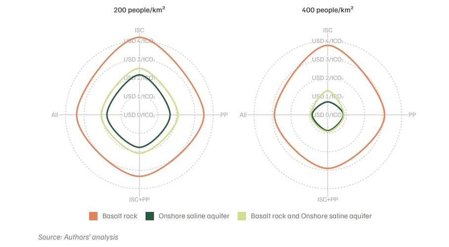
Figure ES1 presents the results of the 24 scenario analyses. The cost of building a CO₂ pipeline network is lowest when only onshore saline aquifers are used and highest when only basalt storage is used. This is because saline aquifers are geographically widespread, while basalt formations are concentrated mainly in Maharashtra and Madhya Pradesh, with some presence in adjoining states. We found that the cost of transport was USD 0.70–2.16 per tonne of CO₂ transported for the saline aquifers–only scenarios and USD 2.89–4.19 per tonne of CO₂ transported for the basalt-only scenarios, depending on the sources included.
When both basalt and saline aquifers were included, transport costs fell within the range of USD 0.87–2.51 per tonne of CO₂. This figure is slightly higher than the saline aquifers–only scenario because, in some cases, the model selected higher-capacity sinks when basalt and saline aquifers are both co-located, leading to fewer pipelines and longer injection durations. Transport costs varied depending on the overall volume of CO₂ transported. Therefore, the scenarios including power plants yielded lower costs than industry-only scenarios. Similarly, the scenarios with a population density of 400 people/km² yielded lower costs than those with 200 people/km² because the sinks are larger, have higher capacity, and are more contiguous, allowing for higher injection volumes. Overall, basalt-only scenarios result in higher transport costs than the saline aquifers–only scenarios. However, post-injection costs are significantly lower in basalt-only sinks (due to the formation of mineral carbonates, which can help eliminate leakage risks), which may offset the higher transportation costs.
Figure ES1. Cost of CO₂ transport is lowest in the case of saline aquifers
The methodology used in this analysis has the following limitations.
CO₂ is captured at the source (such as a power plant or steel mill), compressed to a supercritical state above its critical temperature and pressure, and transported through dedicated pipelines to a storage site. In the supercritical state, CO₂ behaves as a compressible fluid, enabling efficient high-volume transport. The pipeline network consists of large-diameter trunk pipelines, carrying CO₂ from major source areas to major sink areas, and smaller-diameter spur pipelines, connecting individual sources or sinks to the trunk pipelines. Pumping stations are installed at regular intervals (typically every 150 km) to maintain pressure throughout the system.
Right-of-way (RoW) refers to the legal authorisation granted to a project to build and maintain infrastructure on a continuous strip of land. In India, obtaining RoW for a new pipeline requires land acquisition, compensation negotiations with landowners, and regulatory approvals across multiple jurisdictions, often delaying projects by several years. Obtaining permissions to lay pipelines through forest areas, defence lands, coastal regulation zones, and government-owned lands can each take a year or more. This study proposes using the existing RoW of NG pipelines to lay new CO₂ pipelines in parallel, which would significantly reduce these barriers.
This study estimates that the cost of transporting CO₂ through a pipeline network using the RoW of existing NG pipelines ranges from USD 0.70 to USD 4.19 per tonne of CO₂, depending on the emission sources included and the storage sites used. Saline aquifer-only scenarios are the least expensive (USD 0.70–2.16 per tonne), while basalt-only scenarios are the most expensive (USD 2.89–4.19 per tonne). These transport costs are relatively low compared with capture costs, which typically range from USD 30 to USD 100 per tonne, and represent a small fraction of the total CCS chain cost.
Several regulatory and policy actions are required. First, India currently lacks a national CCS policy, and identifying the ministry that will own the mandate is a crucial first step. Second, the Petroleum and Minerals Pipelines (Acquisition of Right of User in Land) Act, 1962, needs to be amended to allow CO₂ pipelines to use existing NG and petroleum pipeline RoWs, and to enable the acquisition of new RoW for CO₂ pipelines. Third, a regulatory authority needs to be established to oversee infrastructure development and safeguard public interests. Finally, an assessment of how much of the existing RoW across NG, crude oil, and petroleum product pipelines can accommodate new CO₂ pipelines is urgently required.
Carbon capture and storage (CCS) is a technology that captures CO₂ emissions from industrial facilities or power plants, compresses them into a supercritical state, and transports them through pipelines to underground geological formations for permanent storage. Suitable storage formations include saline aquifers, basalt formations, and depleted oil and gas fields. CCS is widely recognised as an essential tool for achieving net-zero emissions, particularly for sectors where alternative decarbonisation pathways are limited or prohibitively expensive.
India has committed to achieving net-zero emissions by 2070. However, the energy transition will take several decades, during which fossil fuel-based power plants and heavy industries will continue to emit CO₂. CCS is essential for addressing these residual emissions, particularly from hard-to-abate sectors such as iron and steel, cement, and aluminium, where process emissions cannot be fully eliminated through energy efficiency or renewable energy alone. CEEW modelling indicates that CCS could reduce India’s economic losses by 23 per cent between 2030 and 2050 and by 32 per cent between 2050 and 2100, and could mitigate nearly 60 per cent of emissions from these sectors.
CCS involves permanently storing captured CO₂ in deep geological formations underground, while carbon capture and utilisation (CCU) converts captured CO₂ into useful products such as fuels, chemicals, or construction materials. CCS is generally more cost-effective for large-scale emissions reduction, since underground storage is significantly cheaper than the processes required for utilisation. However, CCU can offer economic co-benefits through the sale of derived products. Both approaches are complementary, and India’s decarbonisation pathway may need to deploy both, with CCS handling the bulk of industrial and power sector emissions.
India has three main types of onshore geological formations suitable for CO₂ storage. Saline aquifers (144 GtCO₂ capacity) are geographically widespread and are the least expensive storage option due to their proximity to emission sources. Basalt formations (170 GtCO₂ capacity) are concentrated primarily in Maharashtra, Madhya Pradesh, and adjoining states. Oil and gas fields and coal formations have a comparatively limited storage potential. Together, India’s total onshore storage potential is estimated at approximately 317 GtCO₂, which far exceeds the country’s projected cumulative emissions over the coming decades.
Basalt formations have a unique geochemical property: when CO₂ is injected into basalt, it reacts with the rock to form solid mineral carbonates over time, a process known as mineral carbonation. This converts the gaseous CO₂ into a stable solid form, virtually eliminating the risk of long-term leakage. Although transport costs to basalt formations are higher due to their geographic concentration, the significantly lower post-injection monitoring and leakage-risk costs may make basalt storage more economical over the full project lifecycle.
Hard-to-abate sectors are industries in which decarbonisation is technically difficult or prohibitively expensive using current technologies. These include iron and steel, cement, aluminium, and chemicals. A large share of their emissions arises from chemical processes rather than from energy use alone, meaning that switching to renewable energy does not eliminate these process emissions. CCS is currently one of the few viable options for addressing process emissions at scale. India’s iron and steel and cement plants alone account for approximately 480 million tonnes of CO₂ per annum that could potentially be captured and stored underground.
Bharat Cleantech Manufacturing Platform: Green Hydrogen Indigenisation Pathways
What is Fuelling India’s Road Transport Sector?

What Drives Vehicle Ownership Costs in India?
How Will India’s Vehicle Ownership Grow?
How can CCUS Decarbonise India’s Industrial Sector?